Question Category

Products

1. Modules

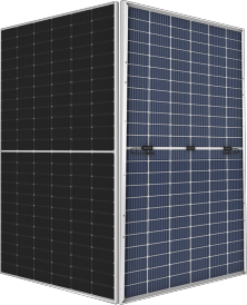
Because of the issue of light leakage in the gaps between the solar cells in double-glass modules, Apex Solar generally uses glazed semi-tempered glass for the backside panel of the double-glass module, with a glazed layer formed into grids where the cells are placed. Because the requirement for accuracy and shading of the glazed layer on the back panel of the cell should be reduced, a certain amount of light leakage is allowed in the industry, without any effect on the quality and energy yield of the product. The inconsistency in light transmittance on the back panel of the single-glass module is caused by differences in light transmittance caused by variations in each model of the back panel of the module. However, when the quality of the back panel meets the certification criteria, there will be no effect on energy yield. Agents will preferentially load the same batch of modules and ship them to the downstream customers.

Customized module are available to meet the special demands of customers, and are in compliance with the relevant industrial standards and test conditions. During the sales process, our salespersons will inform customers of the basic information of the ordered modules, including mode of installation, conditions of use, and the difference between conventional and customized modules. Similarly, agents will also inform their downstream customers of the details about the customized modules.

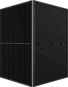
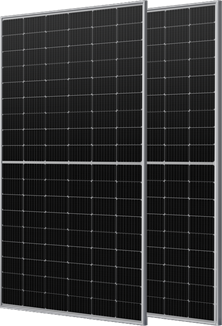
We offer black or silver frames of modules to meet customers’ requests and the application of the modules. We recommend attractive black-frame modules for rooftops and building curtain walls. Neither black nor silver frames affect the energy yield of the module.

Various abnormal conditions may be found throughout the life cycle of modules, including those arising from manufacture, transportation, installation, O&M and use. However, such abnormal conditions can be controlled effectively as long as Grade A products of LERRI are purchased from official suppliers and products are installed, operated and maintained according to the instructions provided by LERRI, so that any adverse effect on the reliability and energy yield of PV power plant can be prevented.

Perforation and welding are not recommended as they may damage the overall structure of the module, to further result in a degradation in mechanical loading capacity during the subsequent services, which may lead to invisible cracks in modules and therefore affect the energy yield.

The energy yield of module depends on three factors: solar radiation (H–peak hours), module nameplate power rating (watts) and system efficiency of system (Pr) (generally taken at about 80%), where the overall energy yield is the product of these three factors; energy yield = H x W x Pr. The installed capacity is caculated by multiplying the nameplate power rating of a single module by the total number of modules in the system. For example, for 10 285 W modules installed, the installed capacity is 285 x 10 = 2,850 W.

Energy yield improvement achieved by bifacial PV modules compared to conventional modules depends on ground reflectance, or albedo; the height and azimuth of the tracker or other racking installed; and the ratio of direct light to scattered light in the region (blue or gray days). Given these factors, the amount of improvement should be assessed based on the actual conditions of the PV power plant. Bifacial energy yield improvements range from 5–20%.

Any distributed modules marketed by us will be accompanied by certificates of conformity, inspection reports and shipping marks. Please ask truck drivers to provide certificates of conformity if no such certificates are found in the packing case. The downstream customers, who have not been provided with such documents, should contact their distribution partners.

Scan the barcode on the module to check the date of manufacture of the module (MM/DD beginning from the 10th digit).

 
Apex modules have been rigorously tested and are able to withstand typhoon wind speeds up to Grade 12. The modules also have a waterproof grade of IP68, and can effectively withstand hail of at least 25 mm in size.

APEX modules have a general warranty of 12 years. Monofacial modules have a 25-year warranty for efficient power generation, while bifacial module performance is guaranteed for 30 years.

APEX, as the world’s leading solar module technology company, has been deeply involved in the residential market for many years and has a strong solutions team. APEX can provide customers with professional project survey, system design, financial advice, power plant construction and acceptance standards, and power plant monitoring operation and maintenance services for the entire life cycle of the project.

APEX took the lead in working with domestic and foreign institutions and customers to carry out empirical testing of bifacial modules for PV power plants, systematically studying the power generation mechanisms of bifacial modules. APEX also leads the industry in bifacial module shipments, surpassing 20 GW+, while providing customers with reference data and technical support.

APEX’s intelligent production network can guarantee the traceability of each module, and our highly automated production lines feature end-to-end inspection and analysis processes to ensure that each module meets the highest quality standards. We select module materials according to the highest standards, with the requirement that all new materials be subject to extended qualification and reliability tests before being incorporated into our products. Third-party labs like RETC and PVEL have ranked our modules among the highest quality products on the market.

APEX has the largest module production capacity in the industry, with more than 50 GW in its integrated capacity network, fully guaranteeing the supply of modules. In addition, the production network facilitates the global distribution of modules with the help of land transportation, railway transportation and sea transportation.

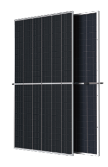
Bifacial modules are slightly more expensive than monofacial modules, but can generate more power under the right conditions. When the rear side of the module is not blocked, the light received by the rear side of the bifacial module can significantly improve energy yield. In addition, the glass-glass encapsulation structure of the bifacial module has better resistance to environmental erosion by water vapor, salt-air fog, etc. Monofacial modules are more suitable for installations in mountainous regions and distributed generation rooftop applications.

Solutions

Power Station

The current and voltage of PV power plants are affected by temperature, light and other conditions. There are always fluctuations in voltage and current since variations in temperature and light are constant: the higher the temperature is, the lower the voltage is and the higher the current is, and the higher the intensity of light is, the higher the voltage and current are. The modules can operate across a temperature range of -40°C–85°C so the energy yield of the PV power plant will note be affected.

Modules appear blue on the whole because of an anti-reflective film coating on the surfaces of the cells. However, there are certain differences in the color of the modules due to a certain difference in thickness of such films. We have a set of different standard colors, including shallow blue, light blue, medium blue, dark blue and deep blue for modules. Furthermore, the efficiency of PV power generation is associated with the power of modules, and is not influenced by any differences in color.

To keep the plant energy yield optimized, check the cleanliness of the module surfaces monthly and regularly wash them with clean water. Attention should be paid to fully cleaning the surfaces of modules to prevent formation of hotspots on modules caused by residual dirt and soiling, and the cleaning work should be carried out in the morning or at night. Also, don’t allow any vegetation, trees and structures that are taller than the modules on the eastern, southeastern, southern, southwestern and western sides of the array. Timely pruning of any trees and vegetation taller than the modules is recommended to prevent shading and possible impact on the energy yield of the modules (for details, refer to cleaning manual).

The energy yield of a PV power plant depends on many things, including the site weather conditions and all the various components in the system. Under normal service conditions, the energy yield depends mainly on the solar radiation and conditions of installation, which are subject to a greater difference between regions and seasons. In addition, we recommend paying more attention to calculating the annual energy yield of the system rather than focusing on daily yield data.

The so-called complex mountain site features staggered gullies, multiple transitions toward slopes, and complex geological and hydrological conditions. At the beginning of design, the design team must fully consider any possible changes in topography. If not, modules could be obscured from direct sunlight, leading to possible issues during layout and construction.

Mountain PV power generation has certain requirements for terrain and orientation. Generally speaking, it is best to select a flat plot with a south slope (when the slope is less than 35 degrees). If the land has a slope greater than 35 degrees in the south, entailing difficult construction but high energy yield and small array spacing and land area, it may good to reconsider the site selection . The second examples are those sites with southeast slope, southwest slope, east slope, and west slope (where the slope is less than 20 degrees). This orientation has slightly large array spacing and large land area, and it can be considered as long as the slope is not too steep. The last examples are the sites with a shady north slope. This orientation receives limited insolation, small energy yield and large array spacing. Such plots should be used as little as possible. If such plots must be used, it is best to choose sites with a slope of less than 10 degrees.

Mountainous terrain features slopes with different orientations and significant slope variations, and even deep gullies or hills in some areas. Therefore, the support system should be designed as flexibly as possible to improve the adaptability to complex terrain: o Change tall racking to shorter racking. o Use a racking structure which is more adaptable to terrain: single-row pile support with an adjustable column height difference, single-pile fixed support, or tracking support with adjustable elevation angle. o Use long-span pre-stressed cable support, which can help overcome the unevenness between columns.

We offer detailed design and site surveys in the early development stages to reduce the amount of land used.

Eco-friendly PV power plants are environmentally-friendly, grid-friendly and customer-friendly. Compared with conventional power plants, they are superior in economics, performance, technology and emissions.

After-Sale Consultation

1. Current

The electrolytic bath is the core carrier for the electrolysis of water to produce hydrogen. Generally, the structure of the electrolytic bath is divided into three parts—the main body, anode and cathode. With direct current applied to the bath, oxidation reaction occurs at the interface between the anode and the solution, while the reduction reaction occurs at the interface between the cathode and the solution.

  1. Frame
  2. Front panel glass
  3. EVA/POE
  4. Solar cell
  5. Back panel glass
  6. Sealant
  7. Terminal junction box
  8. Nameplate
  9. Mounting hole
  10. Grounding hole
  11. Drain hole
  12. Barcode The specific layout corresponding to each specific module type is shown in the relevant product manuals.

Modules are classified by rated current, with the information found on the attached labels.

The identifiers of classes of application/protection are: Protection Class: Class Ⅱ (new) = Application Class: Class A (old). The reason to change such identifiers is the change in the standard of certification in the industry. Both the new and old identifiers are available to us, where new or old identifiers to be adopted will depend on the demands of customers for different orders (with new identifiers as default).

It is not clear whether hotspots will be formed due to the effect of shading above the modules. Of course, there will inevitably be an effect of shading on the energy yield.

Perforation and welding are not recommended installation practices since they may damage the overall structure of the module, resulting in a degradation in mechanical loading capacity, which may lead to invisible microcracks in the cells modules and eventual negative impacts on the energy yield.

Dedicated software like PVsyst and RETScreen Expert is used to calculate the energy yield of a PV power plant. As residential projects, Excel or other spreadsheet can be used for a simple estimation, using the. Following calculation: Ep (annual energy yield) = H x P x K1, where H represents the standard daily hours of sunshine in location regions, P represents the installed capacity of the system (kW), and K1 represents the overall efficiency of the system (75-85%). There are many factors that influence the value of K1, including azimuth of installation, inverter efficiency, module degradation, string arrangements, module soiling, etc.

  • Information about distributor of products (name of company, contact person)
  • Information about modules (quantity, nameplate, barcode)
  • Agreement or procurement contract

For any products directly purchased from APEX, please contact our salespersons. For the products directly purchased from our distributors, place directly contact their representatives who will provide after-sales services. If the relevant problems still cannot be solved satisfactorily through the two ways above, please send us the contracts used to purchase the modules, warranty documents and specific details about the problems with the modules, and we will direct your information to the relevant departments.

2. Voltage

The open-circuit voltages of modules are measured under STC conditions (at a solar radiation of 1,000 W/m2 and a temperature of 25°C), while the open-circuit voltages measured by customers may be different from the voltage indicated on the nameplate because of influencing factors such as solar radiation, temperature and accuracy of instruments. Under normal service conditions, the temperature coefficient for open-circuit voltage is about -0.3(-)-0.35%/℃; therefore, the deviation in measured results is associated with the difference between actual temperature and 25°C at the time of measurement. Also, the deviation in open-circuit voltage caused by solar radiation must be within 10%. In sum, the difference between the open-circuit voltage for onsite testing and the actual range indicated on the nameplate should be calculated according to the actual measurement conditions, and generally should not surpass 15%.